- 您现在的位置:买卖IC网 > Sheet目录1221 > IRADK10 (International Rectifier)KIT DESIGN 3-PH 115-230ACV MOTOR
�� �
�
�IRADK10�
�Electrical� and� mechanical� description�
�The� Printed� wiring� board� is� a� double� sided� 100� x� 160� mm�
�board� using� a� mixed� technology� of� SMT� and� through� hole�
�components.�
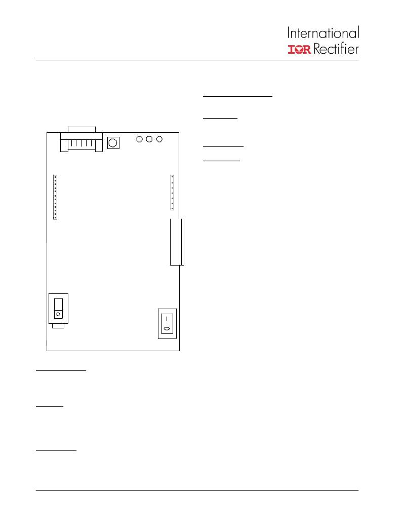
�The� layout� of� the� connectors,� indicators� and� user� controls�
�is� shown� below� in� Figure� 3.�
�HIGH VOLTAGE SIGNALS� is� the� strip� of� pins� with� high�
�voltage� PWM� signals� (i.e.� the� motor� voltages).�
�POWER (J4)� is� the� main� connector� with� the� AC� 115/230V�
�power� supply,� earth� connections� and� the� motor� (A-B-C)�
�connections.�
�RS-232� Serial�
�Link�
�R�
�G�
�Y�
�110V/220V(S3)� is� the� selector� switch� for� the� input� voltage�
�Power Switch� (S2)� is� the� power� switch� to� turn� ON/OFF� the�
�system�
�RS-232� Serial� Link:�
�A� standard� 9� pin� D� connector� is� used� for� the� RS-232� serial�
�link.The� pins� used� on� this� connector� are� the� RxD,� TxD,� GND,�
�RTS,� and� DTR.� The� RTS� and� DTR� signals� provide� sufficient�
�current� to� drive� the� opto-couplers.� The� current� drawn� from�
�these� pins� is� far� below� permissible� limits� for� the� RS232� driv-�
�ers.� The� board� will� communicate� with� the� GUI� tool� (supplied�
�with� the� board),� if� the� drivers� for� the� serial� link� are� already�
�installed.� Notice� that� either� the� COM1� or� COM2� port� of� your�
�PC� has� to� be� available,� the� code� will� not� work� with� COM3� or�
�COM4.� The� serial� cable� may� be� connected� or� disconnected�
�at� any� time� without� having� to� restart� the� computer.�
�LED� board� displays:�
�230�
�Yellow,� Green� and� Red� LEDs� are� mounted� at� the� edge� of�
�the� board.� At� power-up,� the� auxiliary� power� supply� will� oper-�
�ate� if� the� input� voltage� exceeds� 85%� of� rated� voltage.� The�
�yellow� LED� will� flash� for� normal� bus� voltages� above� 60VDC�
�indicating� “DC� bus� voltage� present”.� If� the� drive� is� enabled�
�Figure� 3� Connectors� and� indicators� layout�
�RS-232 Serial Link� :� 9-pin� female� standard� shell� (DB9)�
�connector� provides� for� an� opto-isolated� RS232� serial� link�
�with� the� PC� at� a� fixed� rate� of� 2400� Baud,� no� parity,� 1S� +�
�1S.�
�R,G and Y� are� three� LED� diodes� (red,� green,� yellow)� to�
�reflect� the� drive� status.�
�The� yellow� diode� blinks� when� the� bus� voltage� is� present.�
�The� red� diode� lights� on� fault� and� the� green� one� lights�
�when� the� drive� is� ON.�
�PWM SIGNALS� is� the� strip� of� pins� with� low� voltage� (TTL)�
�signals.�
�www.irf.com�
�and� the� motor� is� being� driven,� the� green� LED� stays� ON� indi-�
�cating� “Drive� operational”.� In� the� event� of� a� fault� condition,�
�the� red� LED� activates� indicating� “Fault� condition”and� the�
�green� LED� extinguishes.�
�To� restart� the� system� the� user� can� perform� one� of� the�
�following� operations:�
�1)� Press� the� RESET� push-button� on� the� board� (see�
�below);�
�2)� Click� on� the� reset� command� in� the� GUI� (PC);�
�3)� Remove� and� re-apply� AC� power.�
�The� reset� button� is� located� next� to� the� serial� link� connector.�
�Press� and� hold� this� button� for� 1� second� to� restart� the� micro�
�processor.�
�4�
�发布紧急采购,3分钟左右您将得到回复。
相关PDF资料
IRADK31
DESIGN KIT 1/4 HP DC FOR IR31XX
IRAUDAMP1
KIT REFERENCE DESIGN W/IR2011S
IRAUDAMP4
KIT 2CH 120W HALF BRDG AUDIO AMP
IRCS2277S
DEMO FOR 3-PHASE/380V MOTOR DRV
IRDC2085S-DF
BOARD EVAL CONV DC BUS W/IRF6603
IRDC3038
KIT W/IRU3038 PWM CTRL DDR 14-PI
IRDC3039
BOARD EVAL CTRLR PWM W/IRU3039
IRDC3046
KIT W/IRU3046 DUAL PWM LDO CTRLR
相关代理商/技术参数
IRADK31
功能描述:电源管理IC开发工具 1/4 HP DC brushless Mtr using IR31xx
RoHS:否 制造商:Maxim Integrated 产品:Evaluation Kits 类型:Battery Management 工具用于评估:MAX17710GB 输入电压: 输出电压:1.8 V
IRADK-S10UP60
制造商:International Rectifier 功能描述:
IRAE410
制造商:MURATA 制造商全称:Murata Manufacturing Co., Ltd. 功能描述:PYROELECTRIC INFRARED SENSORS IRA SERIES
IRA-E410
制造商:MURATA 制造商全称:Murata Manufacturing Co., Ltd. 功能描述:PYROELECTRIC INFRARED SENSORS IRA SERIES
IRA-E410QW1
制造商:Murata Manufacturing Co Ltd 功能描述:PYROELECTRIC INFRARED SENSOR - Bulk
IRA-E410S1
制造商:MURATA 制造商全称:Murata Manufacturing Co., Ltd. 功能描述:PYROELECTRIC INFRARED SENSORS IRA SERIES
IRA-E410ST1
制造商:MURATA 制造商全称:Murata Manufacturing Co., Ltd. 功能描述:PYROELECTRIC INFRARED SENSORS IRA SERIES
IRA-E420
制造商:MURATA 制造商全称:Murata Manufacturing Co., Ltd. 功能描述:Dual Type Pyroelectric Infrared Sensor